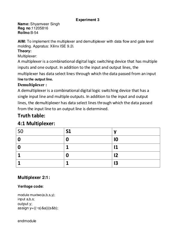
4X1 MUX VHDL source code
In this post, we will take a look at implementing the VHDL code for demultiplexer using behavioral architecture. First, we will take a look at the logic circuit of the 1:4 demultiplexer. The VHDL code, which implements a 2: 1 multiplexer, is illustrated in Figure 7.4. The clause with–select–when is used as a select signal assignment to switch between the two inputs. Figure 7.2 Graphical Symbol of a 2 M: 1 Multiplexer. Figure 7.3 2:1 Multiplexer. Figure 7.4 VHDL Code for a 2: 1 Multiplexer Using Select Signal Assignment. SIMULATION OF VHDL CODE FOR DEMULTIPLEXER Design and develop an 8 output de multiplexer. Simulate the same code in the software For more details:https://www.
This page of VHDL source code covers 4X1 MUX vhdl code.
VHDL Code
use IEEE.STD_LOGIC_1164.ALL;
use IEEE.STD_LOGIC_ARITH.ALL;
use IEEE.STD_LOGIC_UNSIGNED.ALL;
entity depun_mux_out is
Port ( in1 : in std_logic; -- mux input1
in2 : in std_logic; -- mux input2
in3 : in std_logic; -- mux input3
in4 : in std_logic; -- mux input4
sel : in std_logic_vector(1 downto 0); -- selection line
dataout : out std_logic); -- output data
end depun_mux_out;
architecture Behavioral of depun_mux_out is
begin
-- This process for mux logic
process (sel, in1, in2, in3, in4)
begin
case SEL is
when '00' => dataout <= in1;
when '01' => dataout <= in2;
when '10' => dataout <= in3;
when '11' => dataout <= in4;
when others => dataout <= '0';
end case;
end process;
end Behavioral;
USEFUL LINKS to VHDL CODES
Refer following as well as links mentioned on left side panel for useful VHDL codes.
D Flipflop
T Flipflop
Read Write RAM
4X1 MUX
4 bit binary counter
Radix4 Butterfly
16QAM Modulation
2bit Parallel to serial
RF and Wireless tutorials
Share this page
Translate this page
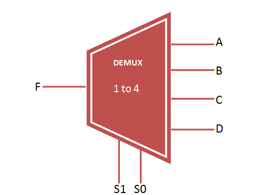
VHDL Code for 1 to 4 DEMUX | 1 to 4 DEMUX VHDL Code
This page of VHDL source code section covers 1 to 4 DEMUX VHDL code.The block diagram and truth table of 1 to 4 DEMUX VHDL code is also mentioned.
Block Diagram of 1 to 4 DEMUX
Truth Table of 1 to 4 DEMUX
1 to 4 DEMUX VHDL code
use ieee.std_logic_1164.all;
use ieee.std_logic_arith.all;
use ieee.std_logic_unsigned.all;
entity demux1_4 is
port (a_in: in std_logic;
sel: in std_logic_vector (1 downto 0);
y_out: out std_logic_vector (3 downto 0));
end demux1_4;
architecture behavioral of demux1_4 is
begin
process (a_in, sel)
begin
case (sel) is
when '00' =>y_out (0) <=a_in; y_out (1) <= '0'; y_out
(2) <= '0'; y_out (3) <= '0';
when '01' => y_out (0) <='0' ;y_out (1) <=a_in; y_out
(2) <= '0'; y_out (3) <= '0';
when '10' => y_out (0) <='0' ; y_out (1) <= '0';y_out
(2) <=a_in; y_out (3) <= '0';
when '11' => y_out (0) <='0' ; y_out (1) <= '0'; y_out
(2) <= '0'; y_out (3) <=a_in;
when others =>null;
end case;
end process;
end;
USEFUL LINKS to VHDL CODES
Refer following as well as links mentioned on left side panel for useful VHDL codes.
D Flipflop
T Flipflop
Read Write RAM
4X1 MUX
4 bit binary counter
Radix4 Butterfly
16QAM Modulation
2bit Parallel to serial


USEFUL LINKS to Verilog Codes
Following are the links to useful Verilog codes.
Low Pass FIR Filter
Asynchronous FIFO design with verilog code
D FF without reset
D FF synchronous reset
1 bit 4 bit comparator
All Logic Gates
RF and Wireless tutorials
Vhdl Code For 1 To 4 Demultiplexer Using Structural Modelling
Share this page
